Speedy mill Next

Speedy mill Next CAD

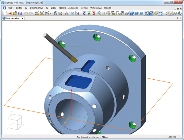
Collaboration of the Traditional 2D CAD and the Global Standard 3D Kernel

2D Data Drawn on the Frame (Plane) = 3D Data

Completely equipped with drawing functions of 2D CAD "Speedy". Having powerful features: data management by frame, powerful modification feature of dimension, detailed drawing and drawing frame that are essential for creating parts drawing, and creating a section view and flattening trihedral figure from the model.

Design Mode - Realizing an Intuitive Operation by Direct Modeling

Enable you to change design and import data from other CAD easily due to the non-history based. 2D element auto split function embedded in the trace supports the natural modeling. Aggregated menus represented by Extrude and modification menus like Remove ad Repair Faces reduce the burden on designers.

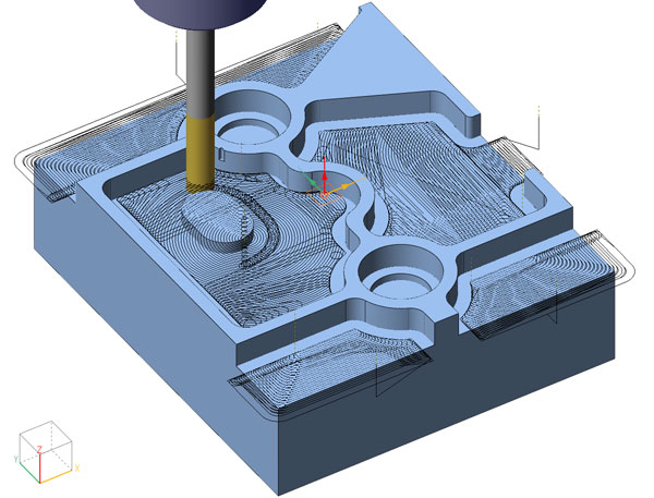
Part Mode - Parametric Design by Constraints and Histories

"Part mode" is a parametric modeling focused on the standard parts and the similar parts. Give the dimension, angle, and distance constraint to 2D shape and make it deform. Enter the value and set it to the variable expression for inputting 2D shape and 3D model, then deform the shape by the history operation. Entering the nominal diameter and passing the value from the variable table are also available.

2D milling

The Great Possibility that "Machined Shell" and "Stock" Realize

Generate Toolpaths with less Stock and Air Cuts

Calculate the "Stock": the change of workpiece after machining. Obtain Z axis machining start position and Z axis retract amount from the stock. Generate more secure toolpath with less air cuts.

Product
Product
Material Cutting Allowance Shape
Stock
Stock

Profiling and Multi-plane Milling

Recognize the concave, convex, and open part from the model and machine the shape with islands and steps all at once. Enable you to select the various machining methods depending on the workpiece in addition to Contour or Pocket.

Pocket Milling (Open)
Pocket Milling (Open and Closed)
Pocket Milling (Closed)

Hole Milling

Select from three types depending on the machine tools and the data of the workpiece.

2D Milling (2D) - Hole Milling
2D Milling - Multi-plane Hole Milling
2D Milling - 5 Axis Hole Milling

High Speed Pocket Milling

Minimize the load on the tool and realize the step-down and high speed feed than before by the toolpath like peeling the surface of onion.

By always cutting into the workpiece with an arc approach, the high-shock load of when cutting can be minimized. Control the wear of tool and the generation of heat. Generate the ideal toolpath for the machine tools.

High Speed Pocket Milling

Multi-task Machining

Multi-task Machining with an Innovative Operation on 3D CAD

The basic structure is the Turning and 5 axis positioning machining for the Multi-task machining. However, require all CAM functions such as 3 axis and 5 axis machining depending on the workpiece.

B axis - Tilt Face and Side Face

The machining direction from the reference plane is automatically calculated by specifying face (function) of 2D milling. Realize the indexing of machining surface by B and C axis with natural operation.

Rotary Profiling

Create a development diagram of cylinder in 2D drawing and output NC code based on this. Contouring, Pocket Milling, Rest Milling, Grooving, and Starting Hole are available.

Simultaneous 3 axis machining

3D CAM that Weaved a Know-how of Machining Over Years

All systems including 3 axis and 5 axis machining are in-house development. CAM operation is integrated. A variety of Roughings that cuts out of workpiece effectively and Z-level Finishing/Scan Line Finishing that output a proper toolpath detecting the wall and the horizontal part are prepared. Clean Up Milling and Morphing are useful for the part where the accuracy and the surface roughness are demanded.

Machine the Compound Curved Surface at once

Automatically calculate the machining part from the material by the specified machining method and finish the product.

Realize a Combination of 2D Milling and Simultaneous 3 Axis Machining

Speedy mill Next manages all machinings from 2D Milling to 5 axis machining by "Stock". Calculate the next toolpath from the material shape of having finished the previous machining. This makes it possible to mix 2D milling and 3 axis machining.

Simultaneous 5 axis machining

Fusion of 4/5 Axis Machining and Positioning Simultaneous 3 Axis Machining

In 5 axis Machining functions such as Parallel, Morphing, and Swarf for Roughing and Finishing, and Pencil for the partial finishing, the way of outputting the toolpath, controlling the tool axis, and checking the interference with a fine control are the most important. In addition, defining 3 axis machining with 5 axis positioning and the 5 axis machining at the same time are essential for the flexible and efficient machining and the guarantee of accuracy.

5 Axis Morphing and 5 Axis Parallel

5 Axis Morphing is the most basic machining that the tool runs along the path generating face.
5 Axis Parallel is a simplified version of Morphing. Perform the Morphing based on the certain axis and plane without defining the path generating face.

5 Axis Swarf

Move the tool so that the side face of tool runs along the path generating face (ruled surface) and finish with efficiency.

DieWorks

There is a Basic Structure Used Over Years for the Die Structure. It is Essential to Create a Database for the Efficiency of Press Die Design and Making, Including the Machining of Plates.

Strip Layout

Create a blank shape by developing the product model. Place it on the stage and specify the bending. Draw a cutting punch and a material width by 2D drawing, then a strip layout can be created from them.

Making a Die Layout by 2D Drawing

Plan the position to place the parts such as lifters, guide posts, and pilot punches, and the position to embed the bending dies on the top view, then draw them.

Draw, Modify, and Move

Call the standard parts from the database, and place them on the plate, At the same time, add the machining information to the plate and modeling standard parts shapes and mounting holes for plates. If you changed the plate thickness, the parts shape and the mounting hole shape will be changed by performing the recalculation.

Interference Check

In "Die Opening", when the material moves per stage pitch, check whether to interfere with the parts that were placed on the bottom die plate or not. In "Die Closing", check the interference between material and plates, material and parts, and plates and parts. The result of check is displayed in 3 types of colors that represent "Interference", "Warning", and "Coincidence".

Pagetop